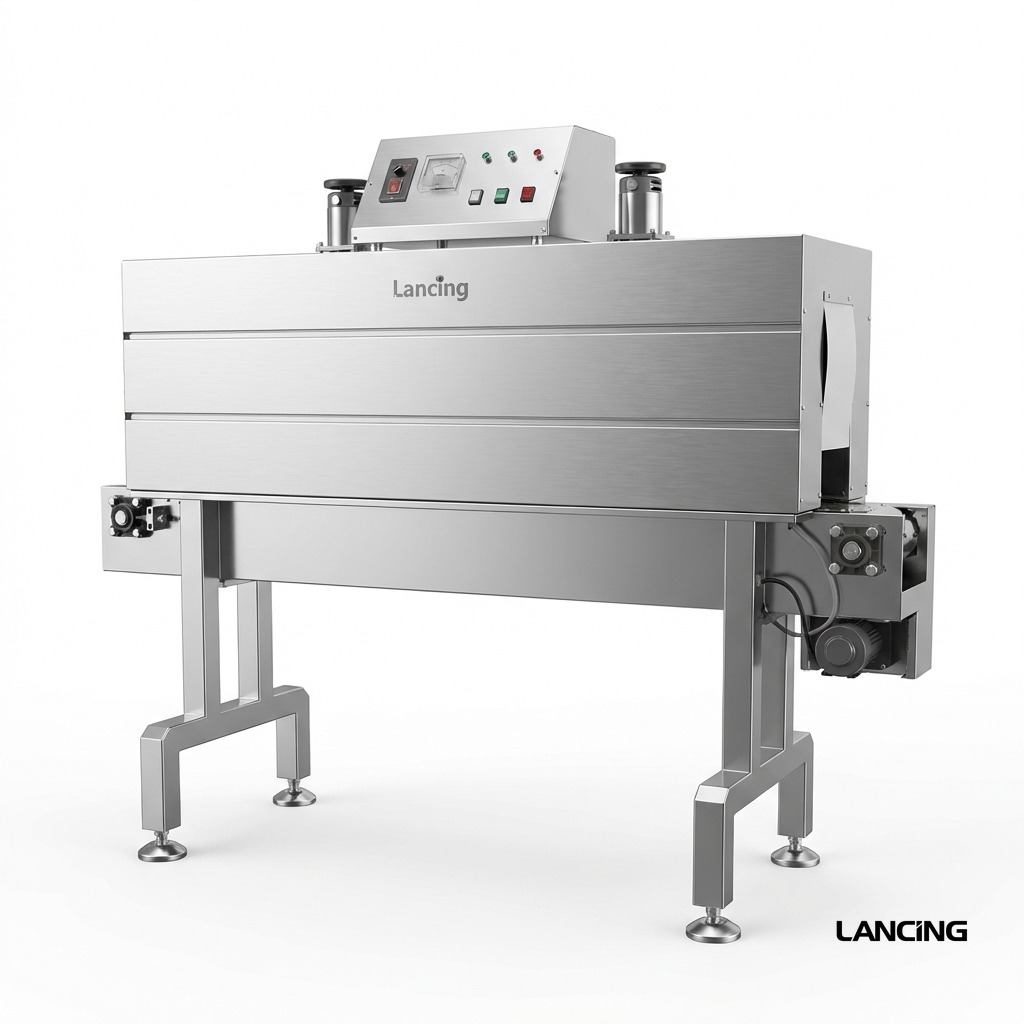
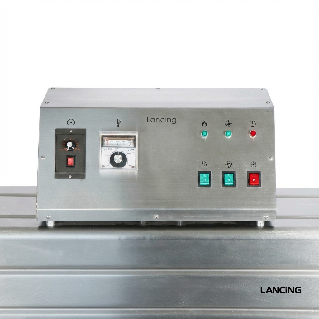
Automatic Film Heat Shrinking Machine
Heavy duty heat tunnel for PE, PVC and POF film on cartons, beverage packs and larger products.
- Output
- 0–15 m/min
- Format
- Product size up to 500 × 350 mm; loading up to 50 kg
Heat tunnels
Heat tunnels control temperature, airflow and conveying speed after the sealing stage. They are selected around film type, product dimensions, tunnel aperture and output target.

Available machines
Compare the relevant machines and send your pack details for a practical recommendation.
Heavy duty heat tunnel for PE, PVC and POF film on cartons, beverage packs and larger products.
Bottle label shrink tunnel for sleeve labels on glass bottles, plastic bottles and similar containers.
Adjustable bottleneck sleeve shrinking machine for neck labels and tamper-evident band applications.
Confirm pack dimensions, desired finish, film type, target throughput, upstream equipment, changeover expectations and available site utilities. This avoids selecting a machine that looks suitable on paper but struggles with the real product.
Lancing can consider conveyors, infeed timing, pack spacing, tunnel discharge, coding and downstream accumulation so the shrink wrapping machine works as part of the wider line.
Technical selection guidance
A reliable heat shrink tunnel creates a repeatable heat-transfer window around the wrapped product. The correct result is achieved by balancing the film shrink curve with the tunnel aperture, airflow pattern, conveyor speed, product load and cooling after discharge.
The published specifications below help shortlist equipment, but final settings must be developed on the intended film and product. Where heat could affect contents, labels, closures or container shape, the sample trial should include the most sensitive production condition.
Measure the wrapped pack at its widest and highest point, including loose film before shrink. The tunnel aperture needs safe running clearance and the conveyor must support the product without leaving pressure marks or allowing small items to fall between rollers or mesh.
For a mixed-format line, check every change part and guide position against both the smallest and largest product. A physically large tunnel is not automatically the most controllable or energy-efficient choice.
The film supplier’s shrink curve shows how contraction develops with temperature and exposure. Tunnel dwell time is the heated length divided by conveyor speed; for example, changing speed changes the time available for the film to respond even when the temperature set point remains unchanged.
Use the curve as a starting point, then establish a safe operating window with the actual pack. Thick products, cold liquid, dense multipacks and continuous loading can absorb heat and alter the result.
Air must reach the leading face, trailing face, sides, top and underside in the correct balance. Excess heat on one face can create holes or distortion while shadowed areas remain loose. Film overlap, perforation and pack spacing also influence how trapped air escapes.
When a defect repeats in the same position, inspect airflow, pack orientation and film presentation before increasing the set temperature. More heat can conceal the cause while reducing the margin to product damage.
Film continues to settle as the pack leaves the heated zone. Stable cooling and sufficient discharge conveyor length help the wrap set before the pack is gripped, stacked or transferred. Heavy PE bundles may need more support than a light POF-wrapped retail carton.
Do not judge bundle strength while the film is still soft. Define the cooling condition and the downstream handling test as part of acceptance.
Record the warm-up procedure, standby settings and normal production loading. A tunnel repeatedly heated from cold for short batches may have a different operating pattern from a continuous line. Door curtains, insulation, extraction and unnecessary aperture clearance can all influence heat loss.
Energy comparison should be made at an agreed product rate and accepted pack quality, not from installed heater power alone.
For each approved product, record film code, temperature zones where applicable, conveyor speed, airflow settings, pack orientation and cooling arrangement. Changeovers should include a first-off sample and a check after the tunnel has stabilised under production load.
Keep the accepted pack or clear photographs at the machine so operators can distinguish a genuine process drift from normal film variation.
| Published model/reference | Temperature and speed information | Aperture/load/application information |
|---|---|---|
| LU-BSP6040 automatic film heat tunnel | 0–15 m/min conveyor; 18 kW; 380 V, 50–60 Hz | 1800 × 600 × 400 mm furnace; product up to 500 × 350 mm; conveyor load up to 50 kg; PE, POF and PVC listed |
| LU-SX403 bottle heat-shrinking tunnel | 0–10 m/min conveyor; 0–250°C; 8 kW | Bottle reference up to 120 mm diameter × 310 mm high; local bottle sleeve/label route |
| LU-SPL4 tunnel reference | 0–15 m/min conveyor | 1800 × 600 × 400 mm tunnel reference used with the bottle multipack wrapping system |
| LU-SPL6 tunnel reference | Automatic line reference; final recipe by product trial | 1800 × 750 × 400 mm tunnel reference; POF and PE listed; 600 mm belt |
| Observed result | Checks before changing the recipe | Controlled adjustment direction |
|---|---|---|
| Loose film or unshrunk area | Film specification, pack spacing, airflow obstruction, tunnel loading and actual belt speed | Change one variable at a time; increase effective heat exposure only within film and product limits |
| Holes, split film or burnt edge | Seal quality, sharp product edges, film gauge, local hot spot and trapped film contact | Remove mechanical causes first; reduce local exposure or rebalance airflow |
| Dog ears or heavy corner fins | Bag size, seal position, film orientation, perforation and corner airflow | Correct film presentation and air evacuation before applying more heat |
| Pack twists or containers move | Infeed alignment, product stability, conveyor support and film pull | Stabilise the group and reduce asymmetric force during shrink |
| Wrinkles after cooling | Film compatibility, shrink balance, pack geometry and cooling support | Confirm the shrink curve and allow the wrap to set before downstream contact |
| Quality changes during a long run | Product temperature, tunnel loading, heater recovery, fan condition and recipe drift | Test under sustained production conditions and document the stable window |
As a practical starting calculation, divide the heated length by conveyor speed using consistent units. The result does not replace a trial because airflow, product load, film shrink curve and temperature stability also affect heat transfer.
Continuous production introduces repeated cold product and changes the thermal load. Check heater recovery, airflow, conveyor speed, product temperature and the number of packs inside the tunnel before altering the recipe.
No. First check film type, bag size, perforation, airflow, belt speed, product spacing and tunnel loading. Increasing temperature without identifying the cause can damage film or product and make the process window narrower.
Provide the smallest and largest packs, the heaviest and most heat-sensitive variants, production film on the intended reel, trays or pads, and an approved example or photographs showing the required finish.
There is no universal clearance figure. The wrapped pack must pass safely without contact while the air system remains effective. Confirm the real loose-film envelope and any product movement during transfer.
Yes, subject to matching conveyor height, width, speed range, product transfer, controls, guarding, electrical supply, extraction and the available cooling/discharge length.
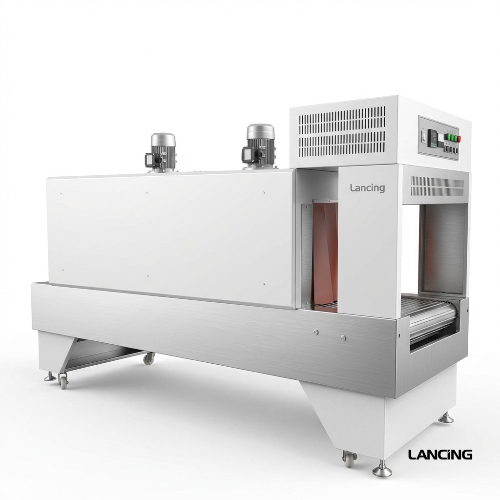
Application review
Send representative packs, the film data sheet, reel sample, required finish, production rate and available conveyor space. Lancing can review the physical envelope and the process variables that need to be proven.
Production acceptance
A useful tunnel trial proves more than one acceptable pack. It records the operating window at start-up, steady thermal load and recovery after normal production gaps so the approved result can be repeated on the factory floor.
Heated path length divided by actual conveyor speed provides a nominal residence-time reference, but it is not a complete measure of heat exposure. Entry and exit effects, belt type, product spacing, airflow direction, load and the product’s thermal mass all influence the film.
Record the measured belt speed rather than relying only on the control display. Where the product changes orientation or passes between zones, describe the complete path used for the accepted sample.
Check the first packs after warm-up, a sustained sequence at the intended pitch, and the first packs after a representative line gap or stop. These states can produce different results because tunnel surfaces, incoming product and the internal air mass may not be at the same equilibrium.
The approved recipe should state when production may begin and what the operator should do after an extended stop. Do not treat a single set-point reading as proof that the complete process has recovered.
The controller set point is one input. Heater condition, fan performance, airflow restriction, door or curtain position, product loading and conveyor speed determine how much heat reaches each face of the pack. A change in pack quality may therefore require mechanical checks before any recipe adjustment.
Keep changes within the machine manual, risk assessment, film supplier guidance and product temperature limits. Adjust one controlled variable at a time and retain the previous accepted setting.
Assess the pack after the film has cooled, not only at the tunnel exit. Warm film can be marked by guides, rollers or accumulation pressure and an apparently tight bundle can relax or distort while setting.
Record the discharge support, cooling distance, pack spacing and the first downstream contact. Include any lift, stack or transfer test that represents the pack’s real handling route.
| Acceptance check | Evidence to record | What a failure may indicate |
|---|---|---|
| Wrapped-pack clearance | Maximum loose-film dimensions, orientation, guide positions and usable aperture | Contact, snagging, unstable tracking or uncontrolled airflow around one face |
| Steady-state loading | Product pitch, actual conveyor speed, consecutive accepted packs and incoming product condition | Insufficient heater recovery, changing airflow or a recipe proved only at light load |
| Gap and restart recovery | Defined stop or gap duration and number of packs required to return to the accepted result | Thermal overshoot, under-recovery or an unclear operator restart method |
| Heaviest or coldest pack | Pack weight, product temperature, film code and accepted appearance | Uneven heat demand, excessive dwell or a narrow process margin |
| Film reel change | Supplier, material, gauge, width, batch and comparison with the approved reel | Different shrink curve, seal window, perforation or tracking behaviour |
| Cooling and handling | Cooling distance/time, downstream contact, lift or stack result and final inspection point | Film marking, bundle movement, relaxation or damage after the tunnel |
Compare the published tunnel references on the LU-BSP6040 page, prepare film evidence with the POF, PE and PVC film guide, and define the full acceptance record in the machinery buying guide. Where the issue begins at the seal rather than the tunnel, review the appropriate L-sealer or sleeve-sealer route before increasing heat exposure.
Heat-tunnel engineering
A heat shrink tunnel is a moving thermal process. Stable results come from controlling the production film, actual conveyor speed, dwell time, airflow, pack loading and cooling together, then proving that the window survives normal production changes.
The production film should be assessed over the temperature and exposure window recommended by its supplier. The product, label, closure and any adhesive can impose a lower heat limit than the film itself. The trial must therefore prove both film recovery and product condition.
Record the actual belt speed used for the approved sample. Effective dwell depends on the heated length, speed, product loading and any hesitation at transfers. A displayed set point is only useful when it can be repeated and verified under normal production conditions.
Air must reach the faces and corners that need shrink without creating a local hot spot or moving an unstable pack. Curtains, ducts, fan condition, product spacing and orientation can all alter the result even when the indicated temperature remains unchanged.
Cold, dense or closely spaced packs absorb more heat and may change the tunnel balance during a sustained run. After the tunnel, film continues to settle while it cools. Downstream guides, labels, compression or stacking should not disturb the pack before the agreed handling condition is reached.
| Stage | Evidence to record | Acceptance question |
|---|---|---|
| Cold start and warm-up | Ambient condition, warm-up time, empty-running checks and the point at which the process stabilises | Can the machine reach a repeatable ready condition without operator guesswork? |
| First-off setup | Film code, temperature, actual conveyor speed, airflow or fan setting, product spacing and orientation | Does the first accepted pack meet the agreed seal, finish and product-condition standard? |
| Sustained normal load | Pack rate, spacing, run length, temperature behaviour, rejects and any setting changes | Does quality remain stable once the tunnel is thermally loaded? |
| Production gap and restart | Length of gap, restart sequence and number of packs needed to recover | Can the process restart without avoidable scrap or uncontrolled setting changes? |
| Heavy or cold product challenge | Highest expected thermal load and initial product condition | Does the approved window remain valid at the real production extreme? |
| Cooling and downstream handling | Discharge support, cooling distance, pack temperature or handling condition and next operation | Is the film sufficiently stable before guides, labels, case packing or palletising? |
When a pack is loose, distorted or overheated, record the current condition before changing it. Altering temperature, speed and airflow together can hide the real cause and make the accepted result difficult to reproduce.
Application review
Send the wrapped pack dimensions and weight, production film details, expected spacing, target sustained output, product temperature range and required downstream handling. Lancing can use that evidence to define the appropriate tunnel and trial checks.
Heat-process questions
Tunnel performance depends on the interaction between film, pack geometry, thermal load, airflow, residence time and recovery after normal production interruptions.
No. Increasing the set point may add heat, but it can also narrow the acceptable process window, damage film or product, and hide problems with airflow, spacing, sealing or dwell time. Output is acceptable only when the pack remains within the agreed quality limits throughout a representative run.
Tune temperature together with actual conveyor speed, loading and airflow. The correct setting is the lowest-risk stable process for the production film and pack, not the highest available value.
Product mass, shape, surface area, orientation, spacing and starting temperature change how heat moves around and into the pack. Corners, recesses and unstable faces also alter airflow. The same reel can therefore require a different process window for another product.
Store recipes against both the film identity and the product format. A film name alone is not enough to reproduce the result.
Check the first packs after the gap separately from steady-state output. A gap can change internal temperature distribution, airflow loading and the amount of heat absorbed by products. The line should recover without repeated uncontrolled adjustments.
A useful acceptance run includes normal stops, restarts and the highest expected product loading so recovery is part of the approved process rather than an untested event.
Send the production film, product temperature condition, pack orientation, expected spacing, normal stoppages and downstream cooling arrangement. Send the application details to Lancing.
Tunnel process detail
A stable heat-tunnel result depends on how the pack enters, releases trapped air, receives heat, leaves the conveyor and cools.
Provide the wrapped footprint, weight distribution, base contact, least stable orientation, required actual speed, product pitch, film and discharge transfer. A published width and load are only the first screening values.
Air inside the loose film envelope can balloon the pack and delay film contact. Confirm the seal, bag size, approved perforation or open ends and product cavities before changing temperature or speed.
Yes. Incorrect film identity, edge damage, contamination, loading direction or a change in material condition can alter sealing and shrinking. Compare the reel and approved process before moving the tunnel outside its established window.
Warm film and an unstable bundle can continue to move after tunnel exit. Plan discharge support, cooling and the next transfer so a good tunnel result is not distorted by close guides, compression or accumulation.
Tunnel selection detail
The tunnel must physically clear the loose-film pack, create the required exposure and use a heat-transfer method suitable for the film, container and site.
No. Use the largest loose-film envelope in the actual running orientation, including fins, ballooning, projections, movement and guides. The final cooled pack can be materially smaller than the envelope the tunnel must process.
Heated length and actual conveyor speed combine to provide exposure, but useful dwell also depends on airflow, temperature, film, product thermal load, spacing and recovery. A hotter setting is not a reliable substitute for insufficient or uneven exposure.
Compare them for shrink sleeve labels, neck bands and complex container decoration where the heat-transfer medium changes label recovery and site requirements. Full overwrap and PE bundle shrinking have different pack structures and normally require their own tunnel route.
Yes. Warm film and unstable bundles can move after discharge. The available cooling conveyor, guides, accumulation and first downstream contact determine whether an acceptable tunnel result remains acceptable during handling.